So it's advertised as
SPDT - which means "single pole, double toggle". Toggle = Throw if you are American.
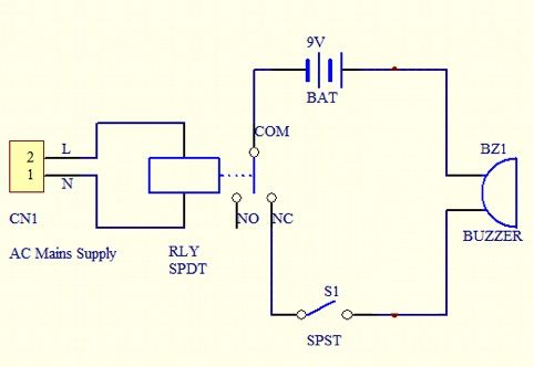
NO is shorthand for "normally open" contact, i.e. an open contact when the relay is de-energised.
NC is "normally closed" while the relay is de-energised, but it appears you have understood that from your diagram.

Maplins pic
It should have five connections. Two of them are for the coil, and the other three are the actual switch.
If it actually has eight connections then it sounds like it's
DPDT, double pole, double toggle.
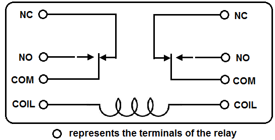 DPDT
DPDTTwo of them for the coil, three for one of the (completely electrically isolated from the other) switches, and the other three for the other switch, there are two separate and electrically independent switches inside.
It doesn't matter whether it is actually SPDT or DPDT, because you only need to use one of the switches and can ignore the other.
It appears that it has a clear plastic case and you can see inside it. If that is true then you should be able to see where the coil is connected to and you can check it with a test meter on resistance setting to confirm that.
Is the coil designed to be operated with 240V? Or when it says it's a 15A/240V relay, does that actually mean that it is
certified to switch 240V? There is a difference! This distinction does not readily throw itself at you since they also say it's a 15 amp relay (not a 15A coil!). Presumably the coil
IS designed to operate with 240 volts, so let's assume that. If it's actually a 12 V coil, well so what? It will just blow up if you try on 240!
Having identified the coil connections, apply power to it and you should see and hear the relay toggle. For each switch there are three contacts. One of them will be the common connection and the other two connections will be the normally open contact and the normally closed contact. You can identify which is which quite easily with the test meter, or as the case is clear, you can visually see for yourself without even testing it.
So you need to identify the two contacts for the coil and two connections (COMmon and NC) to one of the switches - use one switch and ignore the other one, which you will not require. NO will be unused.
Here are the connections you need.
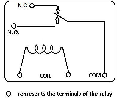 SPDT
SPDT
Are you sure there are no markings next to each of the connections? There might be some tiny embossed lettering in the plastic moulding by each connection which may give you a clue, but in any case you should be able to check it with your test meter and visually if the outer case is transparent as illustrated.
Personally I would avoid using a buzzer that needs a 9V battery, it would be handy to use something a little more practical in terms of battery voltage requirements.
Edit - Ah, yes it actually has a 240 V coil, here are the relevant specs at the bottom of the page.
Coil details:
Nominal voltage: AC 240 V
Operating range(V): 192-264
Coil resistance: 15700Ω±5%
Current at nominal voltage: 14mA
Edit 2 - they do have a download spec. sheet but it covers a number of different types, none of which appears to be the one illustrated on the main page! As it is a plug-in relay, I would guess it will have eight pins for physical security of mounting, but if it is actually SPDT then three of those connections won't be connected to anything inside. I'm sure you'll be able to see what is what by looking through the case.